

TONYA DISPLAY LIMITED
News
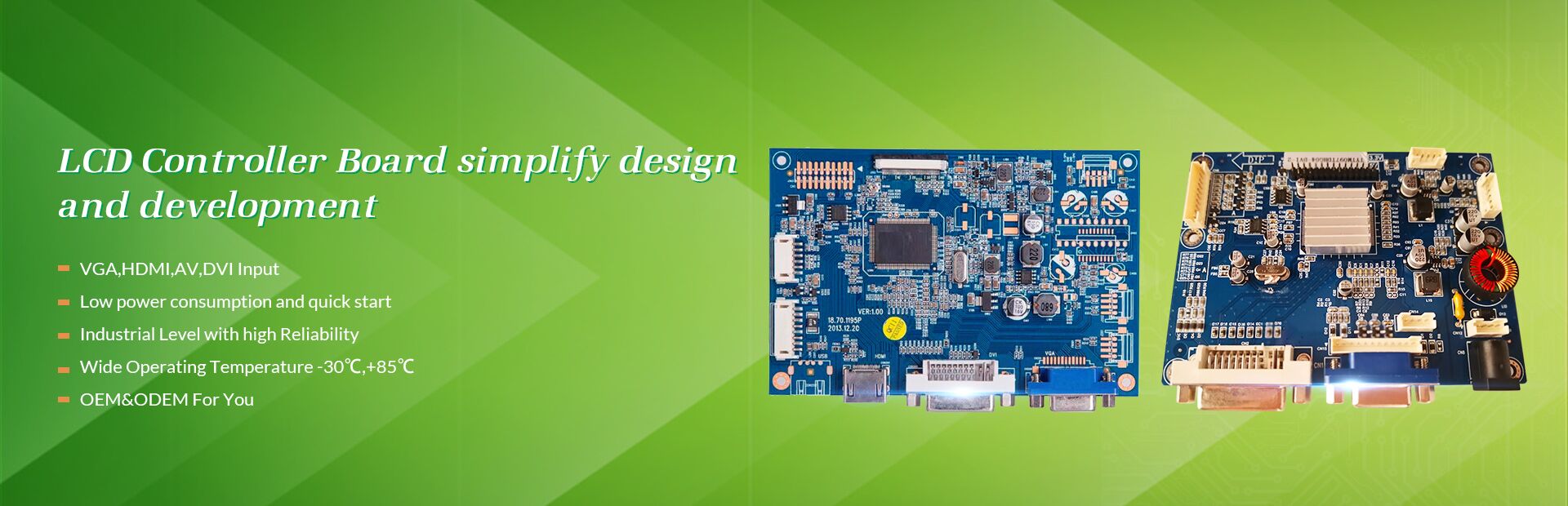
- What is an LCD controller?The LCD controller is a chip or circuit specially used to control the LCD screen. The LCD controller is responsible for receiving image signals from the host device and converting them into signals suitable for LCD screen display. It adjusts the transmittance of light by controlling the liquid crystal molecules on the LCD screen to display images. Its workflow can be simply divided into the following steps: Input image signal: The LCD controller receives image signals from the host device, such as HDMI, VGA, DVI, etc., as input data. Image processing: The controller will process and optimize the input image signal to adapt to the characteristics and display requirements of the LCD screen. This may involve adjustments to image brightness, contrast, color saturation, and color space. Liquid crystal dot matrix control: The LCD display is composed of many small liquid crystal dot matrices. The controller will control each liquid crystal dot based on the input image data. The control of liquid crystal points mainly adjusts the light transmittance by changing the arrangement of liquid crystal molecules, thereby achieving image display. Timing control: The LCD controller also needs to control the timing of the LCD screen, that is, transmit image data to the LCD screen in a specific time sequence. This is very important to ensure the stability and smoothness of the image. Other function control: LCD display controller may also have other functions, such as touch screen control, multi-screen display, backlight control, etc. The core components of the LCD controller include Image Processor, Timing Controller and LCD Driver. The image processor is responsible for digital signal processing and optimization of the input image signal to improve image quality. The timing controller is responsible for timing control and transmission of the processed image data to ensure the stability and fluency of the image. The LCD Driver drives each liquid crystal lattice by outputting appropriate voltage signals to control the arrangement of liquid crystal molecules to achieve image display. In short, an LCD controller is a chip or circuit used to control LCD screen display. It is responsible for processing and optimizing the image signals transmitted from the host device, and realizing image display by controlling the liquid crystal dot matrix on the LCD screen. Liquid crystal display controllers are widely used in modern electronic products and have become an important part of display technology.
2023 10/17
- Basic introduction of OLEDBasic introduction of OLED Definition and advantages of OLED OLED, an Organic light-emitting Diode, is also known as Organic Electroluminesence Display (OELD). OLED is regarded as the next generation of flat display emerging application technology due to its excellent characteristics of spontaneous light, no backlight, high contrast, thin thickness, wide viewing Angle, fast response, flexible panel, wide temperature range, simple structure and manufacturing process. OLED display technology is self-luminous, using a very thin coating of organic materials and a glass substrate that emits light when an electric current flows through it. OLED display screens have a large viewing Angle and can save power.
2022 12/19
- LCD touch screenLCD touch screen The two transparent metal layers of the four-wire resistance technology work with a constant voltage of 5V for each layer: one vertical direction and one horizontal direction. A total of four cables are required. Features: High resolution, high speed transmission response. Surface hardness treatment reduces scratches, scratches and anti-chemical treatment. With smooth and matte finish. One time calibration, high stability, never drifting. The base layer of the five-wire resistive technology touch screen adds the voltage fields in two directions to the conductive working surface of the glass through the precision resistance network. We can simply understand that the voltage fields in the two directions are applied to the same working surface in a time-sharing manner. The outer nickel-gold conductive layer is only used as a pure conductor, and the position of the touch point is measured by the method of time-sharing detection of the X-axis and Y-axis voltage values of the inner ITO contact point after touch. The five-wire resistive touch screen requires four leads on the inner layer of ITO, and only one conductor on the outer layer. There are 5 lead wires for the touch screen. Resistive touch screen, using pressure sensing for control. The main part of the resistive touch screen is a resistive film screen that fits well with the surface of the display. This is a multilayer composite film. It uses a glass or hard plastic plate as the base layer and is coated with a layer of transparent oxide metal (transparent conductive Resistance) conductive layer, covered with a hardened outer surface, smooth and scratch-resistant plastic layer, and its inner surface is also coated with a layer of coating, there are many small (less than 1/1000 inch) transparent isolation between them Point to separate the two conductive layers for insulation. When the finger touches the screen, the two conductive layers are in contact at the touch point, the resistance changes, signals are generated in the X and Y directions, and then sent to the touch screen controller. The controller detects this contact and calculates the position of (X, Y), and then operates according to the way of simulating a mouse. This is the most basic principle of resistive technology touch screens. Therefore, the resistive touch screen can be operated with harder objects. The key to resistive touch screens lies in material technology. Commonly used transparent conductive coating materials are: ITO, indium oxide, with a light transmittance of 80%. When it is thinner, the light transmittance will decrease, and it will rise to 80% when the thickness is 300 angstroms. ITO is the main material used in all resistance technology touch screens and capacitive technology touch screens. In fact, the working surface of resistance and capacitance technology touch screens is ITO coating. Nickel-gold coating, the outer conductive layer of the five-wire resistive touch screen uses a nickel-gold coating material with good ductility. Due to frequent touches, the outer conductive layer uses a nickel-gold material with good ductility. The purpose is to extend the service life but The process cost is relatively high. Although the nickel-gold conductive layer has good ductility, it can only be used as a transparent conductor. It is not suitable for the working surface of the resistive touch screen because of its high conductivity and the metal is not easy to be very uniform in thickness. It is not suitable for the voltage distribution layer and can only be used as a probe. Floor. The capacitive technology touch screen uses the current induction of the human body to work. The capacitive touch screen is a four-layer composite glass screen. The inner surface and the interlayer of the glass screen are each coated with a layer of ITO. The outermost layer is a thin layer of silica glass protective layer. The interlayer ITO coating is used as the working surface, and the four corners lead out Four electrodes, the inner ITO is a shielding layer to ensure a good working environment. When a finger touches the metal layer, due to the electric field of the human body, a coupling capacitor is formed between the user and the surface of the touch screen. For high-frequency current, the capacitor is a direct conductor, so the finger draws a small current from the contact point. This current flows from the electrodes on the four corners of the touch screen, and the current flowing through these four electrodes is proportional to the distance from the finger to the four corners. The controller calculates the ratio of these four currents to get the touch point position.
2021 01/06
- Camera Module (CCM)Camera Module (CCM) 1. IR Filter This is because the human eye cannot see the infrared light, but the sensor senses it. So the infrared light in the light needs to be filtered out so that the image is closer to what the human eye sees. Sensors, Sensor The sensor is the core of the camera. It is responsible for converting optical signals passing through the Lens into electrical signals, and then converting them into digital signals through the internal AD. Each photoreceptor can only sense one kind of light, and these primitive Data are called RAW Data. Raw Data Data through the ISP (can be understood as the Image Sensor Processor, is part of the Sensor module) treatment to restore the three primary colors, that is to say, if a pixel Sensor is R value, then the ISP will be according to the photosensitive around the G, B value, through interpolation and special effects, etc., to calculate the R point G, B value, so that point of RGB is restored, in addition, the ISP still has a lot of operation, which is described below. Currently, there are two commonly used sensors. One is the CCD (charge coupling) component; One is the CMOS (metal oxide conductor) component. CCD (Charge Coupled Device), charge-coupled Device sensor:Made of a highly sensitive semiconductor material that converts light into electrical charges that are converted into electrical signals via an ANALOg-digital converter chip. A CCD consists of a number of independent photographic units, usually in megapixels. When a CCD surface is illuminated, each unit reflects a charge onto the component, and the signals generated by all the units add up to a complete picture. A Complementary Metal Semiconductor (CMOS) is a Semiconductor made of silicon and germanium that coexists with N(-) and P(+) grades on the CMOS, and the current generated by these two Complementary effects can be recorded by the chip and interpreted as an image. 2. Image processing chip DSP DSP is an important part of CCM. Its function is to transmit the data obtained from the photosensitive chip to the CPU in a timely and rapid manner and refresh the photosensitive chip. Therefore, the quality of THE DSP chip directly affects the picture quality
2020 12/04
- DisplayPortDisplayPort is mainly used to transfer video, audio, USB and other formats of data information between the source side and the device side (such as a computer monitor). The DisplayPort specification is a free license designed to replace VGA, DVI, and LVDS to provide high-performance video transmission channels. Users can use Adapter compatible with current VGA/DVI display devices. While the functionality supported is similar to HDMI, the goal is to complement HDMI, not replace it. DisplayPort consists of three separate related standards: a peripheral DisplayPort(externalDisplayPort Interface) standard and two internal interfaces DisplayPort standards: Embedded DisplayPort(eDP) and internalDisplayPort(iDP). Since 2010, the External DisplayPort Interface has made some headway in the mobile PC and PC display markets. EDP is mainly used for mobile and embedded devices; IDP is similar to eDP, but is mainly used in digital TELEVISION equipment. EDP and iDP are designed in their respective fields to replace LVDS The DP interface (DisplayPort) is an image display interface that supports not only full HD resolution (1920×1080), but ALSO 4K resolution (3840×2160) and the latest 8K resolution (7680×4320). DP interface not only has high transmission rate, but also is reliable and stable. Signals transmitted by the interface are composed of data Channel signals of image transmission and auxiliary Channel signals of image-related state and control information, including Main Channel (Main Link), AUX Channel (AUX Channel) and Link Training. A special bus, AUX Channel, is provided in DP for the handshake between source and sink. Because the Source is the controller of the process, it makes requests for Sink. The only way for Sink to communicate with the source is to send a pulse in the hot swap detection (HPD) signal. AUX Channel, as an independent bidirectional transmission auxiliary Channel in DP interface, adopts ac coupled differential transmission mode and is a bidirectional half-duplex transmission Channel with a single-direction rate of only about 1Mbit/s to transmit setting and control instructions.
2020 10/23
- Difference between EDP screen and LVDS screenDifference between EDP screen and LVDS screen EDP screen line refers to the screen interface for 0.3-0.5 small space welding flat line, divided into single channel and double channel. EDP screen wire is generally 2 groups of strands, 3 groups of strands, 5 groups of strands, 8 groups of strands. Common eDP screen lines are 2 sets of signal lines (stranded wires) and 3 sets of signal lines. LVDS screen line is divided into standard line and hd line. LVDS screen interface is 0.5 spaced double row, namely JAE FIRE51P HD line. LVDS screen line (standard line) refers to the screen interface with spacing 1.0 and 1.25, and the terminals are assembled by riveting pressure. Common have single 8 line, double 8 line. Single-octaval lines are mostly FIX-30P and DF141.25-30P, while double-octaval lines are mostly fix-30PIN.
2020 10/16
- CameraCompact ModuleCamera module Camera Module, full name CameraCompact Module, short for CCM. CCM consists of four parts: lens, sensor, FPC and DSP. A lens, a DSP, and a sensor are the important components that determine the quality of a camera. The key technologies of CCM are optical design technology, aspherical mirror making technology and optical coating technology. Working principle: The light gathered by lens is converted into electrical signal by CMOS or CCD integrated circuit, and then converted into digital image signal by internal image processor (ISP), which is then processed by digital signal processor (DSP) and converted into standard GRB, YUV and other format image signals. hardware Lens n. Lens is a device that can receive light signals and concentrate them on CMOS/CCD sensor. Lens determines the lighting rate of the sensor. The overall effect is relative to a convex Lens. General structure of the camera lens is composed of a few pieces of lens, points with PLASTIC lens (PLASTIC) and the GLASS lens (GLASS), usually with camera lens the structure are: 1 p, 2 p, 1 g1p, g3p 1, 2 g2p, 4 g, 8 p, etc. The more lenses, the higher the cost; Glass lenses are more expensive than plastic lenses, but glass lenses do a better job of imaging than plastic lenses. indicators 1. The pixel The sensor has a number of light-sensitive units that convert light into electrical charges to form an electronic image of the object. And in the sensor, each light-sensitive unit corresponds to a pixel, the more Pixels, meaning that it is able to sense more details of an object, so that the image is clearer, the higher the pixel, which means the image effect is clearer. 2. The frame rate Refers to the number of images recorded or played per unit time. A series of pictures will produce animation effect if they are played continuously. According to the human visual system, when the playing speed of pictures is greater than 15 frames per second (i.e., 15 frames), the human eye can hardly see the jump of pictures. The flicker will not be detected when it reaches 24 to 30 frames /s (i.e., 24 to 30 frames). Frames per second (FPS), or frame rate, represents the number of times the graphics sensor can be updated per second while in the processing field. A higher frame rate results in a smoother, more realistic visual experience.
2020 09/29
- Digital zoom and Optical zoomThere are two kinds of zoom, one is digital zoom; One is optical zoom. Digital zoom Digital zoom, digital zoom is through the processor in the digital camera, the image of each pixel area to increase, so as to achieve the purpose of amplification. This technique is like using image processing software to enlarge the area of the image, but the program is carried out in the digital camera. Part of the pixels on the original CCD image sensor are enlarged by "interpolation" processing method, and the pixels on the CCD image sensor are enlarged by interpolation algorithm to the whole picture. Optical zoom Optical Zoom, or Zoom, is a digital camera that relies on the structure of the Optical lens. The optical zoom mode of digital camera is similar to that of traditional 35mm camera, that is, the lens is moved to zoom in and out of the scene to be photographed. The larger the optical zoom, the farther the scene can be photographed. Optical zoom is produced by changing the position of the lens, the object and the focus. When the image plane moves in the horizontal direction, as shown in the figure below, the vision and focal length will change, and further scenery will become clearer, making people feel like objects progressing. Obviously, there must be two ways to change the Angle of view. One is to change the focus of the lens. In photographic terms, this is optical zoom. To change the focal length of a zoom lens by changing the relative position of the lenses. The other is to change the size of the imaging surface, the diagonal length of the imaging surface, which in today's digital photography is called digital zoom. shoot The scientific name of continuous shooting function is Continuous shooting, which saves the time of data transmission to capture the shooting time. By loading the data into the digital camera's internal high speed storage (cache), rather than transferring data to the memory card, continuous shooting mode can take multiple photos in a short time. Since digital camera needs to go through photoelectric conversion, A/D conversion and media recording, etc., both conversion and recording need time, especially more time. Automatic white balance The English name of White Balance is White Balance. The color of the object will be changed by the color of the light it casts, and the photos taken in different light situations will have different color temperatures. For example, a photo taken with a tungsten light bulb might be yellow. Generally speaking, CCDS have no way to automatically correct for light changes like the human eye does. White balance means that no matter what the ambient light is, having a digital camera default to "white" means that it can recognize white and balance other colors against colored light.
2020 09/18
- LCD interfaceEDP is a kind of communication interface of computer display screen. The resolution of COMPUTER using EDP display interface is higher than that of LVDS interface. In general, high-definition screen adopts this communication interface, that is, it can realize the function of "wide viewing Angle". EDP and LVDS are video signal interfaces used to connect touch screen or display in INDUSTRIAL PC. The LVDS interface USES a very low voltage swing (about 350mV) to transmit data by differential over two PCB routing lines or a pair of balanced cables, i.e. low-voltage differential signal transmission. It is a digital video signal transmission method to overcome the disadvantages of high power consumption and EMI in TTL level mode. The IPC adopts LVDS output interface, which enables the signal to be transmitted at the rate of hundreds of Mbit/s on differential PCB line or balanced cable. Low voltage and low current driving mode realize low noise and low power consumption. EDP interface is a fully digital interface based on DisplayPort architecture and protocol. It can transmit high-resolution signals with simpler connectors and fewer pins, and can realize simultaneous transmission of multiple data, so the transmission rate is much higher than LVDS. EDP interface features: 1. Microencapsulation structure, which can realize simultaneous transmission of multiple data. 2. No LVDS conversion circuit, simple circuit. 3. Small EMI (electromagnetic interference) with powerful copyright protection function. Take the LCD screen with 1920x1200 resolution and 24bit color as an example. If LVDS interface is used, 20 pairs of data transmission lines are needed. With the eDP interface, only four pairs of wires are needed. It can be seen that the eDP interface has obvious advantages, especially in HIGH-DEFINITION screens.
2020 09/10
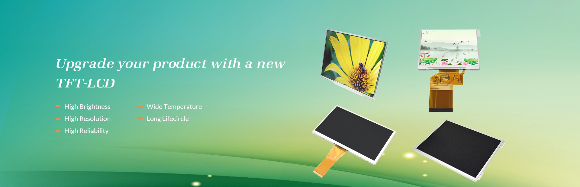
- TFT - LCD profile1. What is tft-lcd TFT - Thin film transistor LCD, Liquid Crystal Display TFT - LCD (Thin Film Transistor - Liquid Crystal Display), Thin Film Transistor Liquid Crystal Display, was born in 1960, through continuous improvement, in 1991 formally applied to commercial laptop. As technology mature gradually, the TFT - LCD in various fields gradually replace CRT products, become the mainstream of Display technology. LCD display is the advantages of small power consumption, low work voltage, high resolution, no radiation, the display itself is thin, easy to carry, long service life, etc., because of these advantages, so has been widely used in many fields, such as televisions, monitors, notebook computers, mobile phones, satellite navigation, PDA, etc. Principle of LCD gray-scale display LCD can be divided into Normal black mode and Normal white mode. Take Normal white mode as an example: when no operating voltage is applied to the liquid crystal, the bar liquid crystal will be arranged in an almost flat position. When the applied voltage on the LCD, LCD will with voltage of different, standing in different angles, the voltage, the greater the Angle stand more steep, the less light penetrates the upper and lower polaroid, vertical stand, until the liquid crystal light almost can't through, appears as dark state. To display each intermediate grayscale simply on the LCD and corresponding voltage, transmittance as imposed on the LCD panel voltage increases and decreases.
2020 08/31
- OLEDThe full name of OLED is organic light emitting diode (OLED). Unlike the LCD mentioned earlier, OLED does not need backlight support. OLED is a kind of congenital surface light source technology. The light can be red, green, blue, white and other monochromatic, so as to achieve the full-color effect. It belongs to a new light-emitting principle. The reason why plasma technology, OLED technology and even early CRT technology are praised for their image quality is that they all have the feature of "self illumination". OLED technology can turn off independent pixels and set their brightness to zero. In theory, the contrast of OLED technology can be infinite. Therefore, OLED is impossible to leak light in black field, so as to improve contrast and image quality. In addition, OLED technology does not need the support of backlight, so the LCD and backlight module are omitted, the structure is very simple, and the body can be ultra-thin naturally, about 1 / 3 of the thickness of the traditional LED screen. OLED also has flexible and bendable features, which can not only be applied to TV, but also make intelligent devices full of imagination space in the future. Combined with the characteristics of OLED thin, the screen can be made as thin as a piece of paper and can be bent and folded at will, which is unimaginable in the LCD era. Finally, whether LCD or OLED, as long as it exists, it has its meaning.
2020 08/24
- VA panelThe full name of VA panel is vertical alignment, which is the panel type widely used in high-end LCD, belonging to wide view panel. There are two kinds of VA, Fujitsu MVA and Samsung PVA. The latter is the improvement and inheritance of the former. Compared with TN, VA has higher contrast, clear and sharp display text, and it can also provide a wider viewing angle and better color restoration. The disadvantage is high power consumption and high price, and VA belongs to soft screen, and ripples will appear when gently scratched by hand. The full name of MVA is multi domain vertical alignment (wide area vertical alignment). It is a multi quadrant vertical alignment technology developed by Fujitsu company. Through technology authorization, Qimei electronics, Youda photoelectric and other enterprises are authorized to produce MVA. However, after the financial crisis, the wide-angle panel manufacturers have encountered a crisis. Qimei and Youda think that MVA has high cost and low profit, so they stop supplying to display manufacturers. LG and Samsung are very market savvy. They used C-PVA and e-IPS with little difference in price and TN to occupy the market of MVA in the past. MVA is characterized by very good visual angle, color and gamut, which is much better than general TN, while the disadvantage is that the response time is slightly poor, but the improved p-mva visual angle is close to 178 °, and the response time can be less than 8ms. The full name of PVA is patterned vertical alignment (vertical adjustment of image), which belongs to the category of va. PVA is the successor and pioneer of MVA, and its comprehensive quality has exceeded that of MVA. The improved S-PVA can even keep pace with p-mva to obtain a very short response time and a very wide viewing angle. PVA uses transparent ITO electrode instead of LCD protrusion in MVA. Transparent electrode can obtain better opening rate, minimize the waste of backlight and reduce the possibility of "bright spot" of LCD. Its position in LCD era is equivalent to "long tube" in picture tube era.
2020 08/17
- Design and development of LCD control driverFor LCD screens, it usually consists of a glass substrate, an ITO(Indium Tin Oxide) film, a directional film, and a polarizing board, with two layers above and below. Each sandwich consists of electrodes and grooves formed on the alignment film, with the upper and lower glass substrates aligned at 90 degrees. Liquid crystals are placed in the upper and lower layers, and the liquid crystals are arranged in the direction of the grooves. On the whole, the liquid crystal molecules are arranged like a spiral twist. When an electric field is added to the glass substrate, the molecular configuration of liquid crystals changes and becomes vertical. When the liquid crystal molecules stand erect, light cannot pass through, resulting in black on the display. Liquid crystal display (LCD) will be based on the voltage, the control of liquid crystal molecular alignment direction, so that the panel to achieve the display effect. There are various classification methods for LCD. Usually according to its display mode can be divided into segment, dot character, dot matrix, etc. In addition to black and white display, there are many grayscale and color display. When driven by LCD, ac voltage is applied to the segment electrode and the common electrode. If only DC voltage is applied to the electrode, the liquid crystal itself degrades. Liquid crystal driving mode includes static driving, dynamic driving and other driving modes. Static drive: Each segment has a separate drive circuit, indicating a continuous voltage applied between the segment electrode and the common electrode. It is suitable for LCD with simple control. Multiple drive mode: a matrix electrode is formed, and the number of common terminals is N. The common terminals are driven in sequence according to the time sequence of 1/ N. Corresponding to the driving sequence, all segment signal electrodes are selected to drive. This method is suitable for LCD with more complex control. In the multiplexed mode, pixels can be divided into selective point, half - selective point and non - selective point. In order to improve the display contrast and reduce cross-talk, duty and bias should be selected reasonably. Multiplexed drive can be divided into point reversal drive and frame reversal drive. The point reversal driver is suitable for low duty cycle applications. It reverses the data when each piece of data is output. The frame reversal driver is suitable for high space ratio applications. It reverses the data when each frame is output. Frame - frequency control (FRC) and pulse width modulation (PWM) methods are usually used for multi - gray and color display control. Frame frequency control is to reduce the number of frame output, control the effective value of the output signal, to achieve multi-gray and color control. By changing the pulse width of the output signal and controlling the effective value of the output signal, the multi-gray and color control is realized. The display mode changes from simple segment type, dot character type to complex dot matrix type and order type. The display color changes gradually from black and white to color. The response time of the display screen is gradually shortened from small to large, and STN display has advantages in cost and consumption current. TFT displays have advantages in contrast and animation corresponding speed.
2020 08/10
- PCBCS control systemAdvantages of PCBCS control system System design, debugging and maintenance is simple, upper information access is very simple and faster, better design of the entire control system. Because PCBCS is an open system, engineers can design the entire control system faster and better based on existing technical achievements and related knowledge. The debugging and maintenance of the whole system is also very simple due to the friendly human-machine interface, simple interface and good universality of components. Also because of PC, information access in the system is very convenient, and the communication between other upper layers is also very simple, relevant information can be done at a glance. The portability of system software is good Although PCBCS has greatly reduced the cost in hardware, it has become relatively difficult in software programming. However, the portability of PCBCS system software is good. It is difficult to compile the software only when doing a new project. If there are other related software for reference or upgrading on the basis of existing software, the software will be easy to compile and the new or upgraded software will be easily developed. Based on the existing PCBCS, software development is no longer a problem. Easy integration of control, human-machine interface and programming functions Because PC has a good human-machine interface, in the control process, various related information is displayed one by one, making it easy for the operator to operate the whole system and realize the overall control. Eliminate the overall adverse factors of control and complete the control task. Moreover, the operator can also carry on the real-time programming, realizes some other system cannot complete the function Shortcomings of PC: For the first time, PC applications are limited in industrial environments. Industrial site environment is relatively harsh, temperature, humidity, dust, electromagnetic interference and many other adverse factors limit the FIELD application of PC. However, the existing industrial grade PC stability has been very high, can meet most of the requirements of the field. In addition, the existing PCBCS mostly avoid the direct application of PC in the field, and mostly adopt intelligent lower computer, such as PLC or other intelligent equipment, but use PC outside the field to control the whole system through fast communication with it. Moreover, in this mode, the communication between each intelligent device is independent of PC. Failure can immediately isolate the failed module, ensuring the stability of the system and avoiding the direct application of PC in the field. Secondly, the stability of PC itself has not reached perfect. Although the performance of PC has been greatly improved and its stability has been greatly enhanced, the PC used in PCBCS requires extremely high stability, which is also an important factor restricting the application of PC in control system.
2020 08/05
- LCD Science PopularizationLet's first look at the LCD LCD is what we usually call liquid crystal. It needs the support of backlight when displaying content, and the backlight will produce polarized light through glass, color filter, optical film, substrate and directional film, which will inevitably cause loss in color and brightness. The full name of TFT is thin film transistor. In LCD, TFT deposits a thin film on the glass substrate as the channel area to improve the image quality. The upper glass substrate is next to the color filter, and the lower glass substrate is inlaid with transistors. When the electric field changes when the current passes through the transistor, the LCD molecule will deflect and the polarization of the light will be changed. Then the polarizer will be used to determine the light and dark state of the pixel. At the same time, the color filter fitted with the upper glass forms the three primary colors of R, G and B contained in each LCD pixel, forming the screen displayed. Simply finished LCD, and then the panel type The full name of TN panel is twisted nematic, and it is also one of many panel types. Because of the low production cost, TN has become the most widely used entry-level panel. At present, the mainstream LCD TVs or displays in the market use TN, and early tablet and mobile phones are also used. Now many users equate TN with TFT, which is a conceptual confusion. Because of its mature technology and low price, TN is still favored by some low-cost products. At the same time, TN with high opening rate can save more power under the same brightness, and the response speed of 8-15ms is also faster. Therefore, under these advantages, even though TN has some disadvantages such as color distortion and narrow viewing angle, it still does not fade out of the market.
2020 08/03
- What is mini led? What is the difference between Mini led and micro led?Mini led, also known as "submillimeter light-emitting diode", refers to the LED with a grain size of about 100 microns, which was first proposed by the Institute of crystal electricity. Mini LED is between traditional LED and micro led, and it is simply an improved version based on traditional LED backlight. Compared with micro led, it has high yield and special cutting characteristics. It can also achieve the form of high curved backlight with soft substrate. With local dimming design, it has better color rendering, can bring more fine HDR partition to LCD panel, and its thickness is close to OLED, which can save up to 80% of power. Therefore, it demands the application of backlight such as power saving, thinness, HDR, special-shaped display, etc, It is suitable for mobile phone, TV, car panel and notebook computer. Compared with microled, in theory, mini LED technology is less difficult, easier to achieve mass production, and can develop a large number of LCD backlight market, with better product economy. According to industry estimates, if the LCD TV panel designed with mini LED backlight is used, the price is only 60-80% of OLED TV panel, but the brightness and picture quality are similar to OLED, and the power saving efficiency is higher. At the same time, a 55 inch Mini led backlit LCD panel uses 40000 LEDs, which will be beneficial to the production capacity of LED grain manufacturers. In general, micro LED will improve the quality of the image, and it is the next generation of revolutionary display technology, but the current technology is still immature. The mini LED is an improved version of LED backlight, but it can still greatly improve the existing LCD screen effect, and the cost is relatively easy to control, which is also expected to become the mainstream of the market. We also expect manufacturers to speed up their R & D and bring micro led and mini LED TV products that can meet the needs of ordinary consumers as soon as possible.
2020 07/27
- Advantages and disadvantages of mini led, micro led and OLEDDespite the manufacturing obstacles, micro LED technology is still worth looking forward to because it provides more progress than OLED. First of all, it is the reduction of power at maximum brightness, that is to say, under the same low power condition, micro LED can achieve greater brightness. In contrast, the power consumption is 90% lower than LCD, and 50% lower than OLED. This is a huge attraction for portable products such as smart phones, which have a very valuable battery life, which means reducing the power consumption of the screen and bringing about longer use time. Compared with current OLED and LCD, manufacturers can increase the brightness of the panel and use it better in direct sunlight. In addition, the display life of micro LED is longer than OLED. OLED screen is still a big problem because of the limited service life of organic materials, especially the blue OLED panel. Micro LED has no such concerns, even longer than LCD before color conversion. And smaller micro led size can also make high-resolution easier to achieve, such as 4K or even 8K resolution smart phones or virtual reality screens. When it comes to virtual reality technology, the response time of OLED panel has been reduced to microsecond level, with a very good response time level. This makes them the best choice for virtual reality applications. After changing to micro led, the response time is further reduced to nanosecond level, 1000 times faster. In addition to the above advantages, micro led also has greater advantages in contrast, color gamut and flexible display. All of these make micro led become an advantage when compared with OLED again, but the manufacturing price cost of micro LED is also much higher, even three to four times of the current LCD or OLED panel. There is no doubt that this will increase the cost of products, and even affect the investment of the whole industry. After all, many manufacturers are still expanding the OLED screen production line.
2020 07/20
- Brief introduction of micro LED technologyThere are many similarities between micro led and OLED, so compared with LCD, the comparison between micro led and OLED is easier to understand. First of all, we can see from the name that there are LEDs, so they are mainly composed of light-emitting diodes. Therefore, both technologies adopt the form of self illumination. Each red, green and blue sub-pixel can generate its own light source, instead of requiring special backlight components like LCD. Therefore, micro LED display can also provide high contrast and black level, which is the same as OLED, and a TFT panel provides energy for each pixel. Micro LED technology, i.e. led miniaturization and matrix technology, is simply to thin-film, miniaturize and array the LED backlight, which can make the LED unit less than 50 microns. Like OLED, each pixel can be individually addressed and independently driven to emit light (self illumination). Its advantage is that it not only inherits the characteristics of inorganic led such as high efficiency, high brightness, high reliability and fast reaction time, but also has the characteristics of self illumination without backlight, small size, light and thin, and can easily achieve the effect of energy saving. From the perspective of structural principle, micro LED is simpler and has better effect. TFT substrate, ultra-fine LED crystal and driving IC are not big problems, but its biggest problem is known as huge transfer. How to miniaturize led requires wafer level technology. For example, 4K level micro LED screens need more than 8 million LEDs to be highly integrated together, so it is extremely difficult to apply them to Small-size screens in theory, and the cost and heating are also very considerable. The 146 inch selection of Samsung's first micro LED TV is also the reason for this. The difference between micro led and OLED lies in the material composition of LED part. "O" in OLED represents organic material, which refers to the use of organic material in the pixel stack that can produce light. Micro LED technology uses inorganic gallium nitride material, which is commonly used in ordinary LED lighting products. This technology can reduce the requirements of polarization and packaging layer, and make the display panel thinner. So the components of micro LED are very small, less than 100 μ m wide, and thinner than human hair.
2020 07/13
- What display technologies are OLED and micro led?OLED (organic light emitting diode), also known as organic light emitting semiconductor display (OLED). OLED is a kind of current type organic light-emitting device, which emits light through carrier injection and recombination. The luminous intensity is directly proportional to the injected current. Under the action of the electric field, the holes produced by the anode and the electrons produced by the cathode will move, inject into the hole transport layer and the electron transport layer respectively, and migrate to the light-emitting layer. When the two meet in the light-emitting layer, energy excitons are generated, which excite the light-emitting molecules to generate visible light. As OLED has long been popular and belongs to a relatively mature technology, it will not be described here. Micro LED technology was created in 2000 by a research group led by two professors, Hongxing Jiang and Jingyu Lin from Texas Institute of technology. Of course, the first time consumers saw the screen using micro LED technology is Sony's 55 inch Full HD resolution "Crystal LED display" product, which was officially unveiled in 2012. At that time, the technology was much better than its competitors in both contrast and color gamut. Of course, but Sony products using this technology are very expensive, and due to the very low production capacity, there is basically no possibility of mass commercialization. But this did not organize companies and enterprises to continue to invest and improve micro LED technology. Industry insiders said that micro LED technology has been very close to the level of commercial mass production.
2020 07/06
Email to this supplier